During my time in Northwestern University’s MSR program, I took a series of Mechatronics courses that covered several aspects of robot design. The capstone of the series was a design project to build a shoebox-sized robotic vehicle from scratch. We would then program it to drive autonomously around a custom race track. My vehicle (affectionately nicknamed Cotton Candy after its color scheme) was designed and built over several weeks worth of time in early 2018. Every aspect of the vehicle creation, including mechanical design, electrical controls (with the motor control board provided by the class administrator), the software running on the microcontroller and an attached Android phone, and vehicle assembly, was ultimately my responsibility during the lead-up to the final demonstration. It was a great way to accrue a variety of cross-disciplinary design experience, and the ‘race’ at the end was exciting for the chance to see all of the other designs and talk about the process with everyone else.
Nick Marchuk, who served as administrator of the NU Mechatronics classes, started our series by kicking us off with workshops that each focused on a specific topic in robotic systems design, such as designing motor controls, digital signal processing for sensor noise compensation, sensor fusion, and mechanical CAD. He also provided us with a small motor control daughter board, designed to work with microcontroller PCBs we were tasked to design, layout, and populate. These would later serve as the brains for our mobile robots. Lastly, we were encouraged to handle our CAD designs through some kind of version control system, so I created an OnShape profile to perform my mechanical design through their online CAD system. I had used SolidWorks to inspect mechanical assemblies before at ATS, so the OnShape interface was very familiar.
With the stage set, the rest of this project write-up just goes through the specific disciplines that featured and will cover my experiences with each. The project repository is over on GitHub which holds the mechanical designs, electrical schematics, and the microcontroller and Android application source code. MPLAB IDE and Android Studio were used for emdedded device programming, and Autodesk EAGLE was used for the electrical schematics and PCB layout.
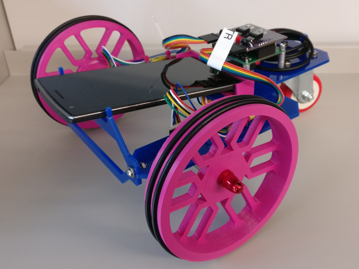

The vehicle itself is a differential drive system, with the wheels driven by two Chihai CHR-16G-050-ABHL 12V, 3.3W DC motors and controlled with a PIC32MX250F128B microcontroller. The Android phone on top (on my vehicle, this phone is a OnePlus One running Android Marshmallow) is needed for its rear-facing camera. The generally-suggested design uses the phone’s rear-facing camera to perform line detection via a custom Android application that was sideloaded onto the phone. The rear caster, 12V lithium-ion battery, wheel collets/caps, and miscellaneous wiring and fasteners were all hand-picked, although in the battery’s case we were given limited options to choose from. All of the mechanical chassis pieces were designed by myself and either 3D printed (with PLA) or laser cut (from cast acrylic sheets).
Mechanical Design
The mechanical design of the vehicle was where I got most creative. All mechanical design was done in OnShape, and you can click on the preview images below to inspect the final detail drawings.
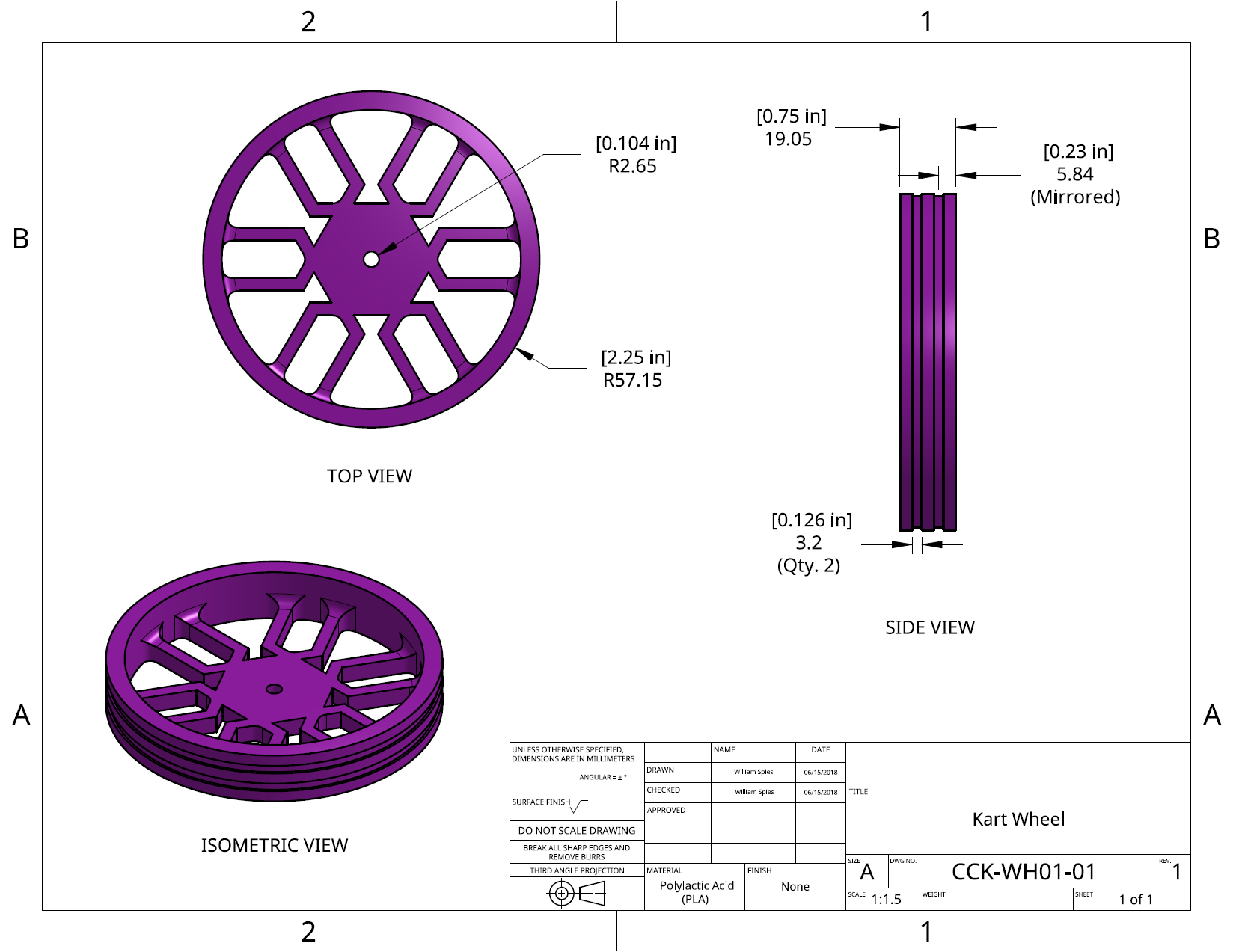
The wheels are a vibrant shade of pink as our 3D printer in the MSR lab only had pink filament available at the time. As it turns out, the use of color gave the finished product a more interesting look (although I wish I had picked out blue wheel hubs, instead of the red ones I settled for). The twin wheel channels for seating O-rings was a savvy idea, as it allowed for more traction and ground contact when compared to some of the thinner wheel designs that only had room for a single O-ring. The trade-off was a longer 3D print time, but the improved performance on inclines was well worth the extra time spent on the print bed.
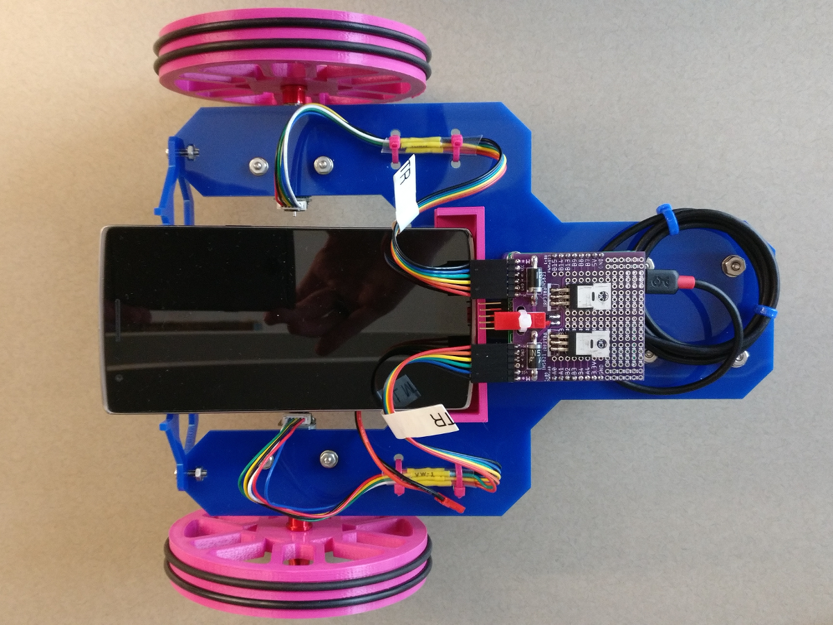
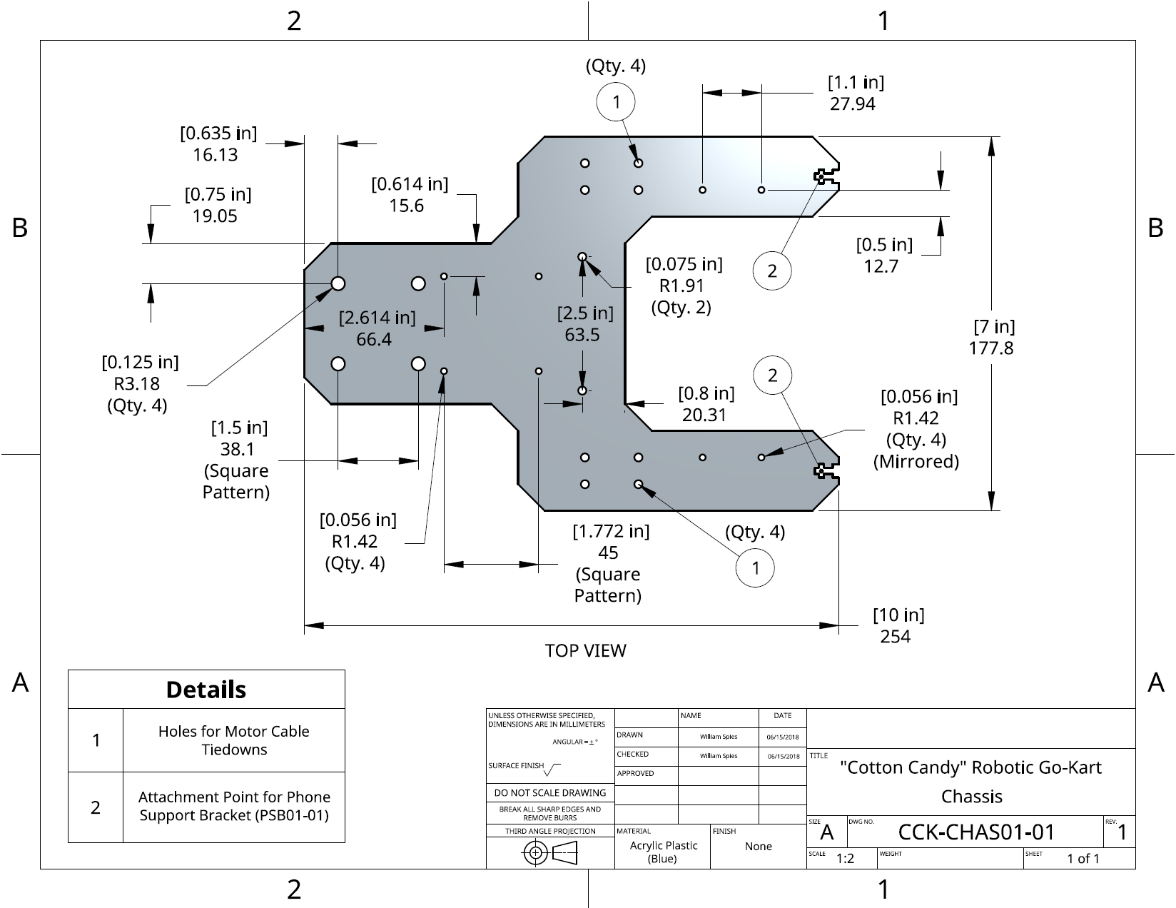
The chassis (both the mounting surface and the front phone support bracket) was cut from a single blue sheet of acrylic. Thanks to the Ford Engineering Design Center’s laser cutters, the mounting holes and other cutout details were a breeze to handle. Hardware was secured with assorted bolts, washers, and nuts, while the motor power/encoder cables were secured with tie-wraps to keep those from moving around when the vehicle was driving.
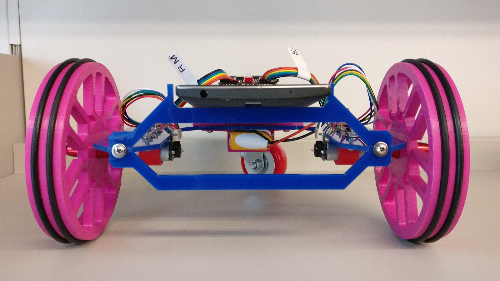
The phone support bracket at the front of the vehicle was specifically designed to elevate the top portion of the phone. With a slight upward angle to the phone, the rear-facing camera is able to look slightly ahead of the drive axis.
The battery and motors are clamped to the chassis with custom-fit, 3D printed pieces. The control electronics are on stand-offs to allow some cable routing underneath, and also to provide a secure mounting point to the rest of the body. As a result of all this, with the exception of the phone’s free movement, the vehicle feels very sturdy.
Electrical Design
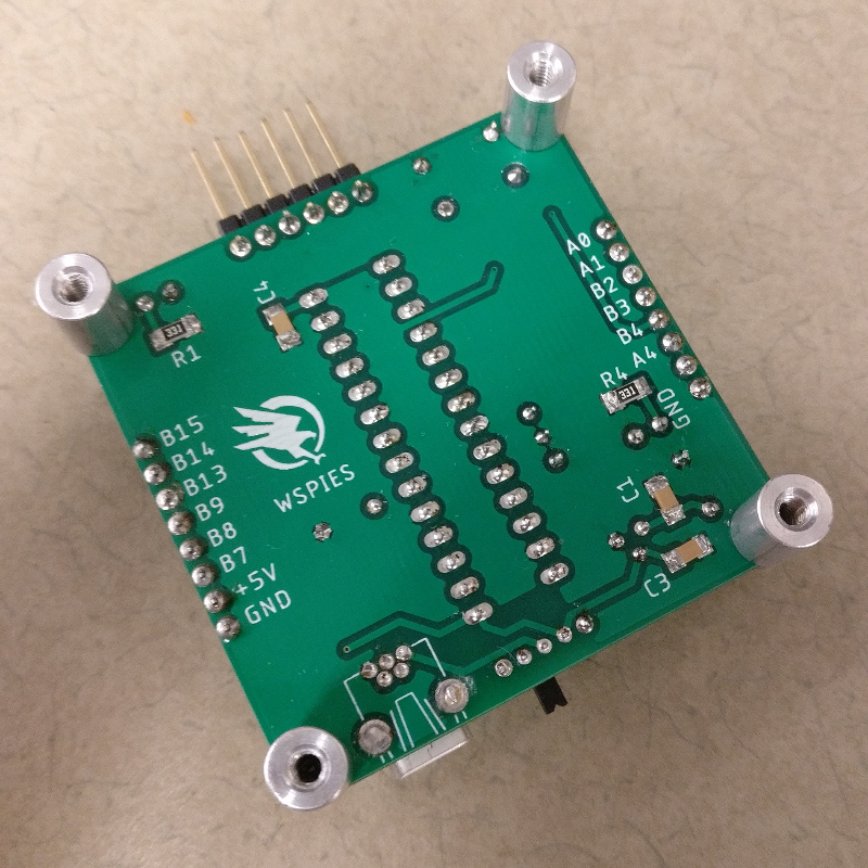
The electrical design was oriented around a few peripheral requirements, most of which involved the need for discrete motor control and a USB OTG interface to the Android phone. As mentioned earlier, core processing was handled with a 32-bit PIC32MX250F128B microcontroller. Most components were sourced from either DigiKey or Sparkfun. The left two images show the final, populated control board, before I mounted it to the chassis.
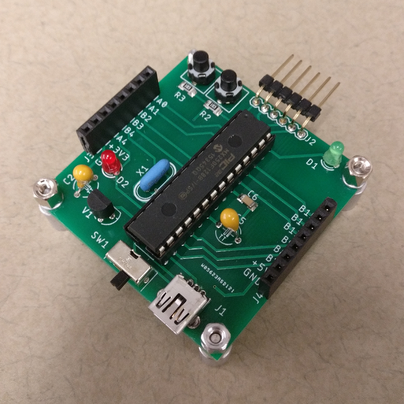
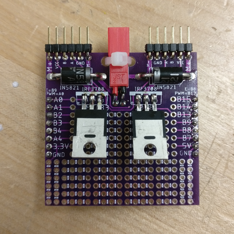
The supplied motor control daughter board, which had a ready-to-go design for PWM motor control, can be seen on the far right. Our responsibilities were simply to populate the board and plug in the peripherals.
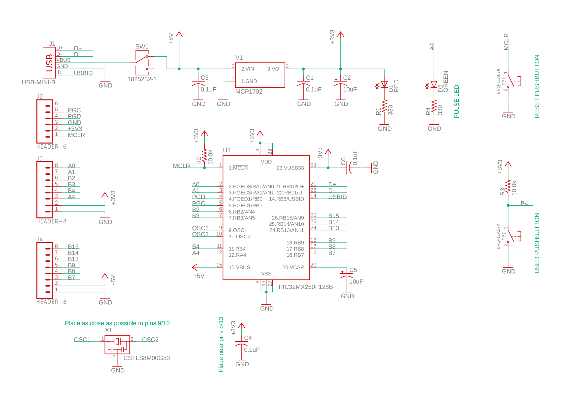
Spacing for the 8-pin header interface provided the only position constraint for the PCB design, though I elected to use surface-mount components in order to cut down the amount of vias needed to connect everything. The system design includes the microcontroller, two status LEDs (one power, one user-configurable), the power supply, two pushbuttons (one master reset, one user-configurable), the programming port, the USB Mini port, and the headers for the motor controller board. Schematic and layout were both done with Eagle, and are shown below.
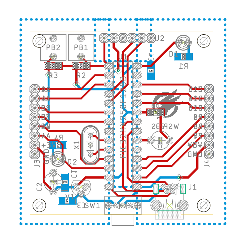
All members of the ME433 class used a third-party PCB manufacturer, PCBWay, to do the board fabrication. I did the all of the soldering and board testing myself, so I was pretty happy when everything powered-up and worked like a charm. I also really like the nice, clean look that my PCB ended up with, and the post holes in the corner were perfect for mounting the board on standoffs, resulting in a secure connection to the rest of the chassis.
Software Design
The software design was split into two distinct parts:
- The main microcontroller program, and
- The line-finding Android application.
The high-level structure of the software is as follows: The microcontroller code, written in C, initializes and sets up an internal state machine.
It then immediately attempts to open a socket to the Android phone via USB OTG.
The microcontroller uses data from the phone application, written in Java, to determine how to drive the motors via a PI control loop.
The system continually runs through the [app<->PI control] sequence until powered down.
The microcontroller uses a single PI controller, looping at a modest (about 50 Hertz) frequency to output two individual PWM signals, one for each motor. The PWM signals are clamped to fall in a range that corresponds to 0-100% motor power. Depending on where the microcontroller “perceives” the line to be, it will raise or lower the left or right motor power appropriately, while attempting to maintain some amount of forward velocity. The PWM frequency itself is set to about 20 kilohertz.
The microcontroller “perceives” the line position by being told where the line falls within the camera’s field of view.
Thanks to Harmony, a set of Microchip-provided libraries, the microcontroller can receive data via USB OTG while a phone application is running.
The Android application intercepts the camera stream and does color segmentation to identify a specific colored line on the track.
In this case, the application is programmed to pick out the red portion of the line.
The application passes along the line position by returning an integer value that represents the line position in pixel coordinates on the rear-facing camera’s image plane.
Since I know how wide the camera image is, I can set pixel values (representing the center of the image) to correspond to equal power applied in the forward direction for both motors.
Everything outside of the center then triggers a scaled change in applied motor power.
There are plenty of other clever things done in the code, such as exposing controls for color saturation and intensity thresholds that can be tuned on the phone’s display, to more easily work around ambient lighting changes.
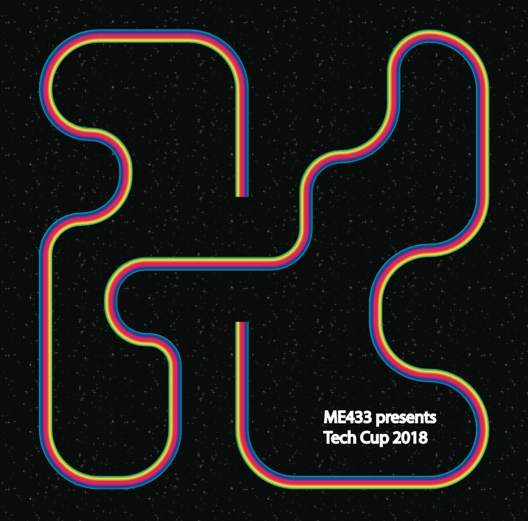
You can see an example of the course at right. NOTE that there is an inclined ramp cross-over, which is placed on the track gap in the center of the image, which connects the vertical straightaway and closes the loop on the track.
As for the competition, my cart traversed the course in just over 2 minutes, which put it into the top quarter of the time trials. The incline cross-over in the middle gave many of the other teams all kinds of trouble, since most of the robots could not generate enough traction to get up the slope, so most of the results ended up being marked down as “Did Not Finish”. My robot achieved fairly strong on-track results, but even just watching the evolution of my vehicle design was well worth the time. I also think it would be a neat extension to come back and iterate on this design, if I come up with a more practical use in the future.